
Hani-Mandl Reloaded.
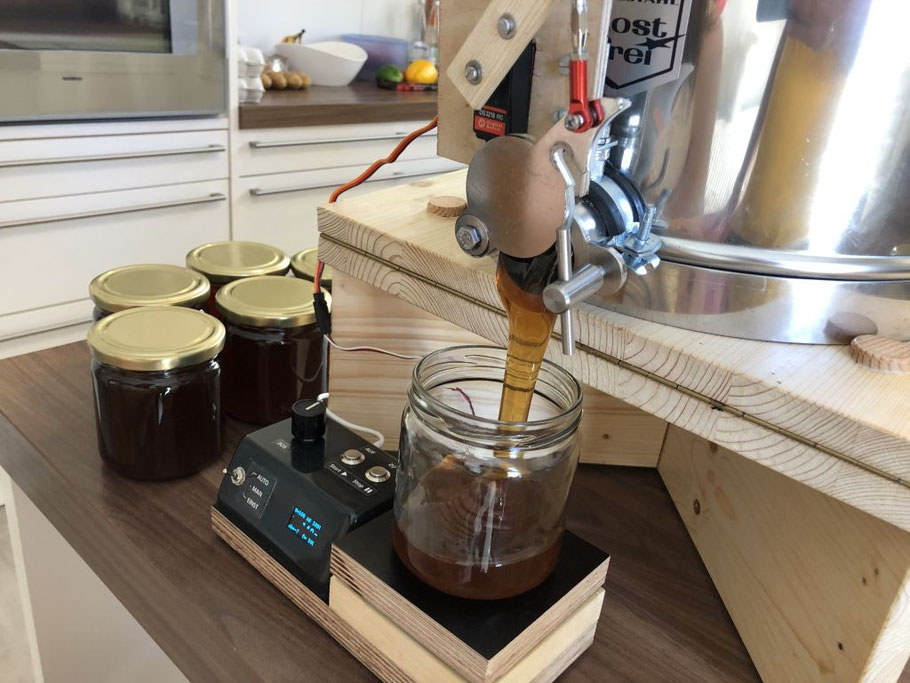
Autumn is the time of year when the garden beekeeper has nothing more to do with the bees and therefore has time to fiddle about, build and invent machines, for example an optimized version of the filling robot Hani-Mandl.
The first version of the filling robot works perfectly, but does not look very professional with the wooden parts.
On the Internet, some enthusiasts presented their own creations, including some who make plastic parts themselves using a 3D printer. Additionally, inspired by a TV documentary about the maker scene, the garden beekeeper began to explore 3D printing and decided to get into this exciting topic.
The Hani-Mandl was to become the familiarization project.
In order to produce the parts, they first have to be designed using 3D CAD software (CAD = Computer Aided Design). The garden beekeeper benefited from the fact that he learned technical drawing as a student and had already bought and used a (2D) CAD program, which is primitive by today's standards, in the 1990s.
After a few test prints on the printers of friends, he quickly bought his own 3D printer to be autonomous.
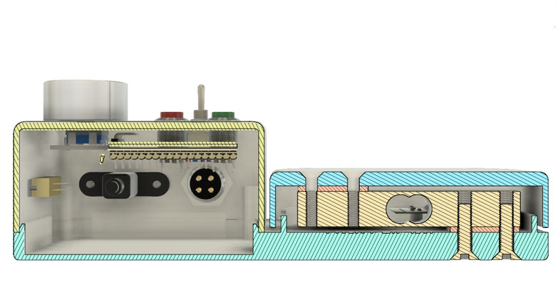
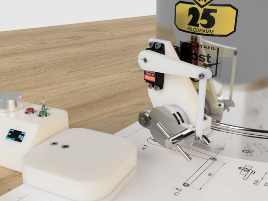
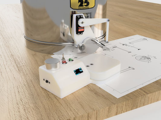
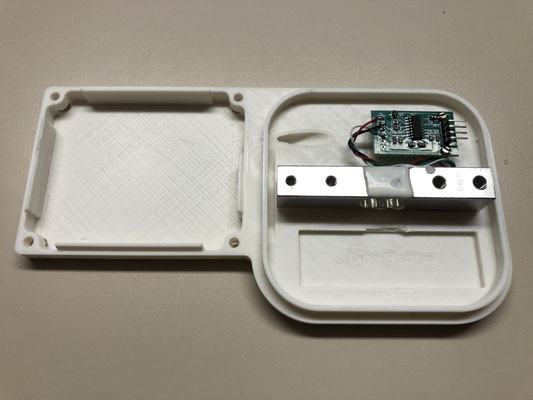
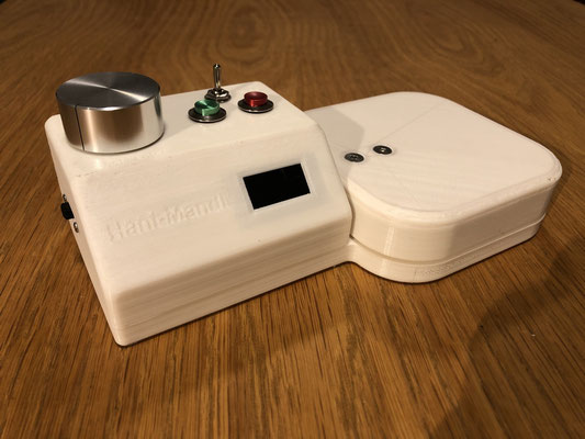
Housing for Scale and Electronics
As with the first prototype, the housing forms a unit with the scale. The microcomputer with display is held in position by clips. The cables are led through a tunnel from the weighing unit into the housing.
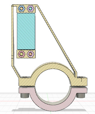
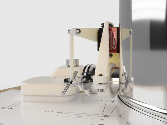
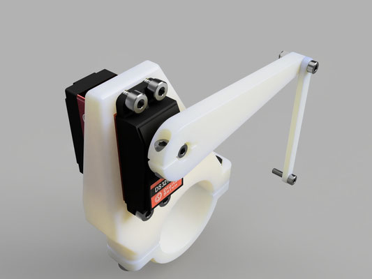
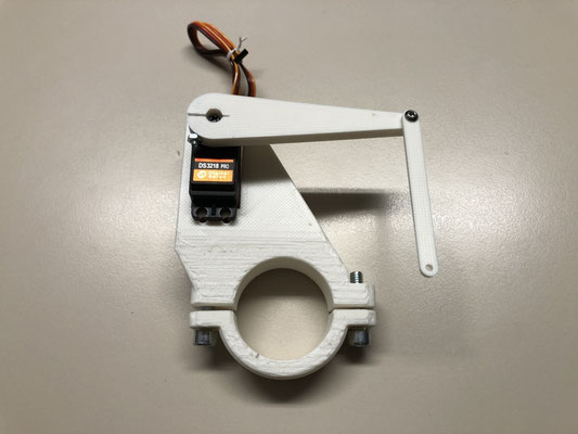
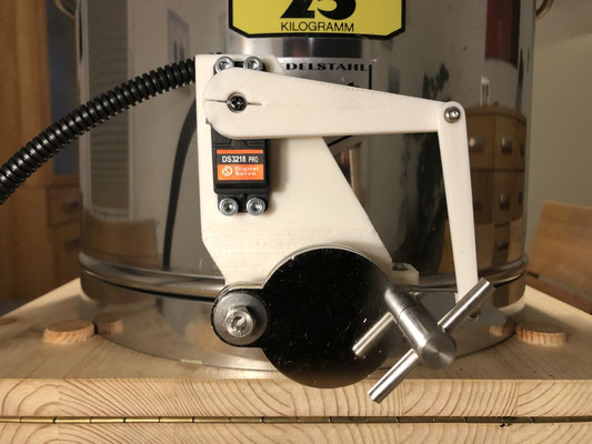
Servo Mount and Linkage
The basic design was created by Michael Kurzweil. Inspired by this, this assembly was redesigned and some details were modified.

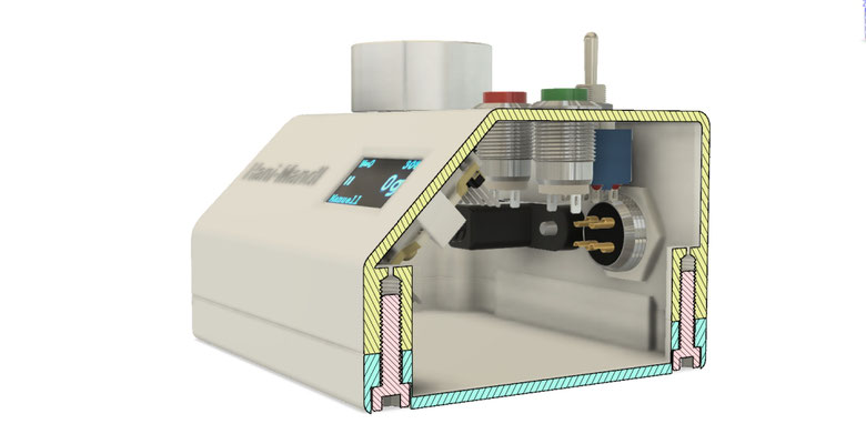
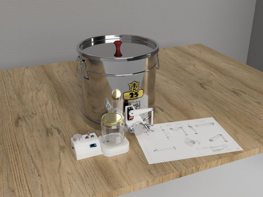
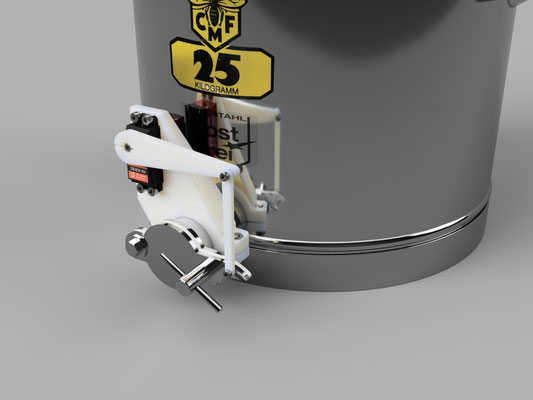
Rendered 3D CAD Objects
The 3D-CAD software allows to generate photorealistic illustrations from the designed objects. Thus, the design can be studied in detail even before production.
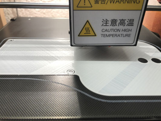
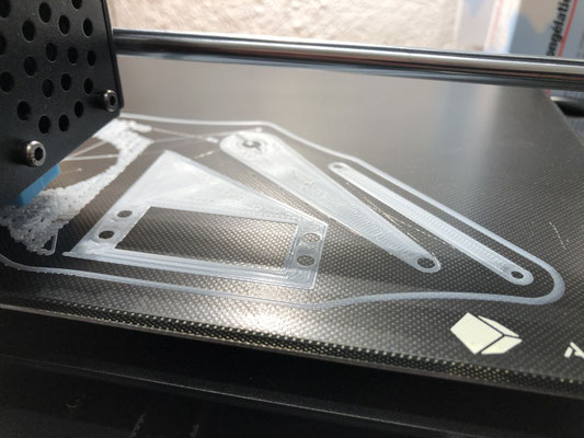
3D Printing of the Components
Finally, the 3D printer "printed" the white plastic objects layer by layer. The printing of the base plate, for example, took 18 hours.
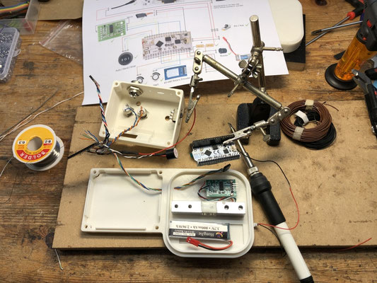
Assembly
The assembly was unproblematic, all parts and the connections fit at first go.
The "real" device differs only slightly from the simulated pictures in the surface texture: On closer inspection, one can see the fine plastic layers that are characteristic of 3D printed objects.
Drawings
When the garden beekeeper learned technical drawing in the 90s of the last millennium, the technical drawing on paper marked the beginning of the product development process.
In this project, the sequence was different: The first idea was sketched with Powerpoint, and on this basis a functional prototype was produced "freehand". In real use of the prototype, further ideas were then developed and details were optimized, these were constructed in the 3D-CAD program "Fusion 360" and the photorealistic images were rendered from these. From the 3D design, the slicer program "Cura" was used to create the print files, which were then produced with the 3D printer. Last mistakes in a part had to be corrected, and only then (!) the technical drawings were generated, and this rather for nostalgic reasons, since nowadays nobody really needs paper drawings anymore.
Unfortunately, the µC somehow was burned during soldering, so no final commissioning could be done yet.

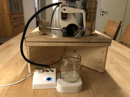
Commissioning
Watch this video showing the device filling some delicious summer honey into jars.

There are no comments yet.